


Virtual production techniques are quickly finding homes within production spaces, and with these new workflows comes new hardware and technical requirements. Some of them familiar, like compositing and green screen integration, many of them not so much, like motion tracking and the LED volume.
In order to make the most of your next virtual production project it’s important that all of these pieces are working together effectively for you. One of the most critical systems for making ICVFX workflows effective is your motion tracking system, there are new options for this popping up frequently, and not all of them are going to work perfectly for your specific needs — if you don’t know which system is best for you no need to worry, we’ve got you covered with all the basics in our previous post The Secret to XR Virtual Production, check it out.
CoPilotXR is a leading virtual production company, pioneering innovative solutions and workflows in the rapidly expanding field of XR and virtual production. With its cutting-edge technology and strategic industry partnerships, CoPilotXR is reshaping the way audiences experience digital content.
Our research and development team works with clients and partners to craft solutions and pipelines for any production.
When it comes to motion tracking we’ve worked with many effective providers, from small-scale solutions like the HTC Vive and Mars series to the worlds smallest motion tracking system found at Antilatency, all the way to big industry solutions like those found at Mo-Sys Engineering through the StarTracker.
In this write-up we’ll be exploring the Mo-Sys StarTracker from unboxing all the way to use in Unreal Engine, keep an eye out in the future for similar breakdowns for other motion tracking systems and integrations.
Understanding the Mo-Sys Star Tracker
The Mo-Sys StarTracker is the first optical solution built from the ground up to address in-studio virtual production camera tracking. The company and their offered solutions have become a staple in the virtual production space for their accuracy, reliability, and consistency.
Their team of engineers are constantly improving upon the existing hardware, with a huge update rolling out later this year and the new StarTracker Max replacing the current generation of trackers, as well as working with creative teams both internally and externally to provide solutions that make the most of what the StarTracker has to offer, like in their VP Pro XR solution that showcases XR applications used for real-time set extension and their Cinematic XR Focus.
The StarTracker itself is the key to unlocking the potential of most virtual production workflows.
All that said, I’m going to show you how to set up a Mo-Sys Star Tracker in virtually any space. Let's get started!
Components in the Mo-Sys Star Tracker Box
We’re going to breakdown the numerous components that you should expect to find included with your StarTracker once it arrives:
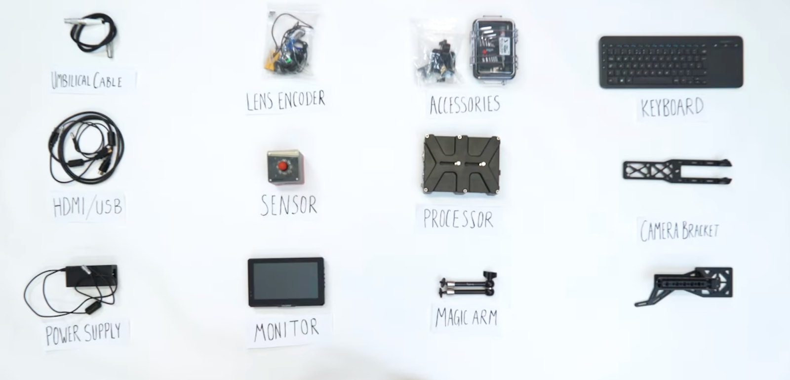
- Of course you’ll have the StarTracker itself — This is the core component that when paired with the retroreflective stars tracks positional data and translates it for use in 3D software and real-time engines. An ultra wide camera sensor ensures it’s able to collect as much positional data as possible at any moment.
- Retroreflective Stars — these laser cut stickers are essential for the StarTracker camera sensor to triangulate and identify position within the physical space.
- Processor — This powers and controls the system and will be mounted under your camera as a platform for your rig. Future versions of the StarTracker will have smaller more streamlined systems meaning your camera rig is about to get cleaner and more light weight.
- Umbilical Cable — Connection between the processor and the sensor.
- Power Supply Unit — Unsurprisingly provides power to your system. Requires a universal power cord.
- Touchscreen Monitor — Allows easy set-up and installation allowing adjustments and calibrations to be done at the StarTracker.
- Wireless Keyboard — Allows more precise interfacing with the System during set-up.
- HDMI/USB Cable — Connects the monitor and keyboard to the processor.
- Magic Arm Accessory — This allows you to mount the Monitor alongside your processor in your camera set-up
- Camera Bracket — Use to securely attach the StarTracker sensor to your camera. They have two options here one uniquely designed for a Blackmagic URSA as well as a universal bracket for any set-up.
- Accessory Peli1020 Case — This container holds any of the necessary tools you’ll need for installing your StarTracker, as well as a digital technical sheet and guide.
There are also optional add-ons you can get with your StarTracker such as the Lens Encoder that allows you to also collect lens data during your production.
Now that we know the components, let's proceed with the setup.
Placing the Stars
Mo-Sys offers various sizes of stars for their StarTracker, and the size you get is important. The required size in most cases is dependant on the height of your ceiling. The higher the ceiling the larger the stars. If you’re ceiling, truss, or wherever you’re installing the stars isn’t at a single height, take the average height between the two.
In some more niche cases the StarTracker can be mounted underneath your camera set-up and then your stars have to be much smaller and installed on the floor of your studio space instead. Installation is more or less the same either way, but the shorter the distance between the camera and the stars the more precise your inputs will need to be to get good data.
In our research space, we’re working with 3m ceilings which means we want the average distance between stars to be about 30cm, and you want the stars to cover your entire production space so that you have the freedom to move the camera anywhere you might need.
The most important aspect of putting up the stars is to avoid creating a grid or a straight line. Instead, place the stars randomly to allow the star tracker to identify unique patterns in the stars.
It’s important to note that many 3D applications, including Mo-Sys, rely on the metric system, so if you're more familiar with the imperial system, buckle up, cowboy!
Setting Up the Mo-Sys Star Tracker
Now that the stars are all installed let’s set the rest up and check out how we did.
Start by grabbing the processor and connecting all the cables to their designated ports. It’s important that you don’t force or connect any cables to the wrong destinations as this can damage the cables or ports making them inoperable.
If you aren’t sure where to connect all the cables you can follow along with Austin in the video below as he walks through this process step by step.
Now that everything is connected it’s time to remove the protective cover from the StarTracker and switch it on.
If everything is connected properly the star tracker will boot up and display the sensors current view as well as the user interface for the StarTracker. You should see that the camera sensor is picking up the stars you’ve placed and new stars should come into view as you move the StarTracker.
Mo-Sys recommends a minimum of 11 stars for operation, but aiming for at least 14 stars provides better accuracy.
Now that the star tracker is functioning, it's time to create a custom map.
Mapping
Creating a map is the StarTracker’s way of understanding its position in space, the scale of the room it’s in, and establish your forward direction. The mapping process is a two step process beginning with initialisation.
Once mapping has begun the StarTracker sensor needs to be placed on a stable surface with a view of the stars placed within your space. If you placed your stars on the ceiling you can place the sensor on the floor, if your stars are on a different plane like the floor, it will be easier to mount the sensor to a roller stand or tripod at the average height for your camera.
To complete initialisation you have to move the StarTracker forward, the distance will be slightly different depending on the size of your space, with our 3m ceilings we had to move our sensor 30cm. The recommended distance will be noted on the screen during the initialisation process.
This process needs to be done with a steady hand, any sudden movements or shaking will cause the system to reject the initialisation requiring you to reset.
It is also important to note that at this stage you want your forward movement to move towards your talent or LED screen or Green Screen, essentially orienting its forward position as your stage area.
Once the sensor has been moved and the initialisation saved, complete the mapping process by walking around your studio with the sensor in hand and collect data on all the stars. You want to try and capture every star from various heights and perspectives so moved rotate the StarTracker as you perform this stage of the mapping.
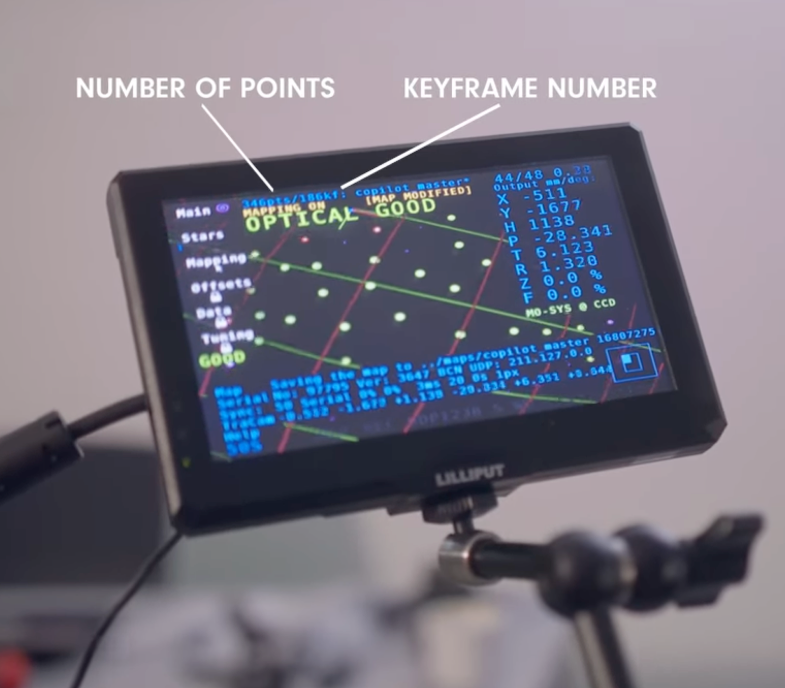
A star has been added successfully to a map from your current viewpoint when it transforms into a pink circle with a green crosshair in the middle.
Pay attention to the number of stars discovered and the corresponding keyframe number. Ideally, you should have about a third as many keyframes as discovered stars for consistent optical stability.
Mounting and Measuring
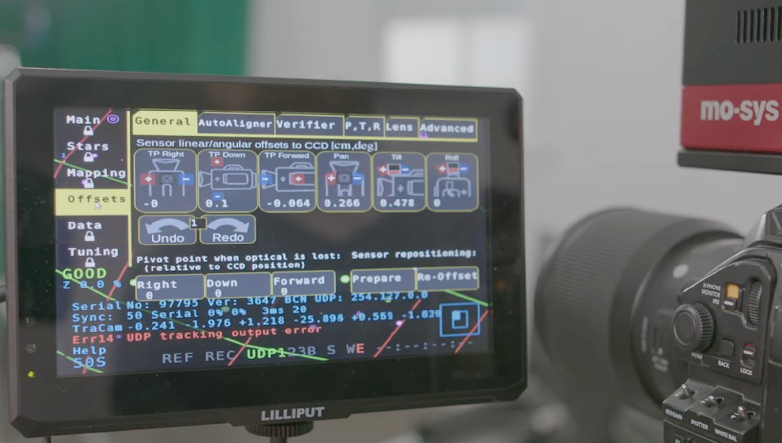
Now that mapping is complete you can mount the star tracker in a convenient location on your camera, considering the camera model's specifications.
Once the system is mounted to your camera rig you need to measure your offsets between the StarTracker Sensor and your camera sensor, this is especially important if you are using this system for in-camera VFX [ICVFX] as it defines the relationship between the StarTracker movements and the Camera’s CCD/sensors.
Calibrating
Calibrating is critical for ensuring you are getting the highest quality tracking data possible from your set-up. With the Mo-Sys system we can quickly and accurately calibrate the system using the auto-align feature.
In order to use this feature we need to start by marking three targets on the floor, creating a right angle, representing the origin point, x-axis, and y-axis. Ensure the targets align with your camera's perspective and are accurately positioned.
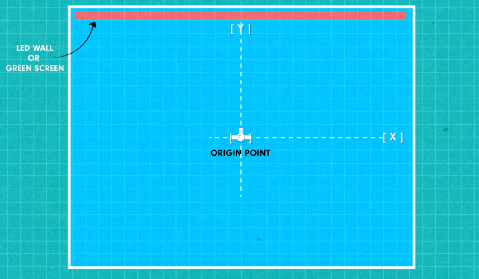
For example, the corner of your right angle would be the origin point with a measurement of (0,0,0), if you added another point to the right of your origin point that was 1.5m away your second point would exist at (1.5,0,0).
It’s also good practice to consider that your positive ‘y’ value should be moving towards your talent or LED wall and your positive ‘x’ value should be moving to the right from the perspective of your camera.
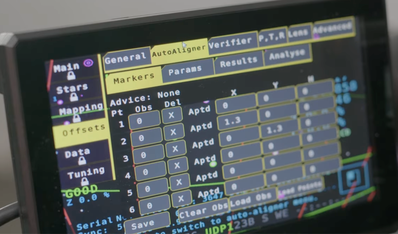
Now that we’ve mapped out our real-world reference co-ordinates it’s time to use through-lens calibration to match the virtual and physical worlds. Assign coordinates to the three points (i.e. origin, x-axis, and y-axis) to prepare to record observations for each target. Observing the points requires a high level of accuracy so if your camera has a centre dot display take advantage of it to make sure you’re always targeting correctly.
Capture observations of your points from different camera locations around the studio to ensure optical tracking remains accurate. Aim for four to six observations per point. Beside each point you’ll see the letters ‘A’, ‘P’, ’T’, and ‘D’ which stands for Angle, Pan, Tilt, and Distance. As you make observations the letters beside each point should disappear signifying you’ve captured enough of a range in data for the system. Your first observation will work as the baseline and the goal with each subsequent observation is to adjust your perspective enough to satisfy the requirement for each category.
After completing the observations, run the calibration process. A calibration success message and an error rate below 1 indicate successful calibration.
Verifying
Before you save your calibration it is important that you verify its accuracy. The verify tool shows where the system believes your camera is looking at in the real world with the correlated virtual co-ordinates. For example, if you were to look at your origin point again you should see a value close to 0 ‘x’ and 0 ‘y’.
With your accuracy verified you can save your map so that anytime you need camera tracking in your space it’s just a click to start.
Congratulations! Your Mo-Sys Star Tracker is now calibrated and ready for all your camera tracking needs.
Sending Data
Now that you have your camera and tracking system set-up you need to send that data somewhere if you want to use it.
To do this you’ll need to set a static IP address for your StarTracker and input the destination IP addresses for any computers that are going to need to receive that tracking data live.
You can change these inputs under the data menu on your StarTracker.
Once you’ve finished mapping out these addresses it’s a good idea to create an IP table referencing each device in your system, especially as your set-up expands that connectivity can start to get complicated.
Once your system is connected to your network, we can send motion tracking data over the network to your 3D engine of choice. For a majority of our set-ups we take advantage of the power and accessibility of Unreal Engine.
In order to take advantage of the tools Mo-Sys has developed for the StarTracker we’ll want to start by downloading and installing the Mo-Sys VP Pro plugin. The basic model of this plugin is free to use and gets you the basic tools you need to translate motion tracking data over LiveLink, higher paid tiers of the plugin provide additional resources and tools for more advanced workflows and project requirements.
Once you’ve downloaded the plugin you can add it to the Plugins folder of your Unreal Project, if you don’t see one in your project directory, create a new folder named ‘Plugins’ and copy Mo-Sys VP Pro into this folder.
Once you open your project, check your plugins and if it isn’t enabled, do that now and restart the project.
Now the project is set-up to receive motion tracking data from your StarTracker, in the LiveLink window you can create a preset for your StarTracker, and you can link it to a LiveLink component on any of the objects in your scene you need to receive the tracking data. In an nDisplay set-up this would be your nDisplay virtual camera for example.
You can now use your StarTracker system in-engine to supplement or enhance your current workflows.
That concludes the tutorial on setting up a Mo-Sys Star Tracker.
I hope you found this guide helpful. Don't forget to like and subscribe to our channel for more exciting content. Good luck with your virtual production endeavours!
Related reads

.jpg)